- CYPE >
- english >
- new features >
- 2010 >
- CYPECAD
CYPECAD incorporates important new features which are indicated below.
- New CYPECAD modules
- Joints III. Welded. Building frames with rolled and welded steel I sections (as of the 2010.a version)
- Joints IV. Bolted. Building frames with rolled and welded steel I sections (as of 2010.k version)
- Joints I and Joints II modules
- Joints I and Joints II in CYPECAD (as of the 2010.a version)
- Trimming of flanges and webs for pinned beam to column web connections (as of the 2010.a version)
- Export to TEKLA Structure, TecnoMetal 4D and in CIS/2 (as of the 2010.a version)
- Check for cracking (as of the 2010.b version)
- New loading behaviour (as of the 2010.a version)
- Other new features
- More updates
Joints III. Welded. Building frames with rolled and welded steel I sections (as of the 2010.a version)
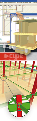
The new module: Joints III. Welded – Building frames with rolled and welded steel I sections allows CYPECAD, Metal 3D and the Integrated 3D structures of CYPECAD to carry out the automatic design of welded connections of common rolled and welded I steel sections in building frames.
More information on the properties of this module can be found in Welded joints for building frames with rolled and welded steel I sections (implement code, type of implemented connections…)
Joints IV. Bolted. Building frames with rolled and welded steel I sections (as of 2010.k version)
The new module Joints IV. Bolted. Building frames with rolled and welded steel I sections allows for the automatic design and analysis of the most common type of bolted connections of rolled and welded steel I sections in CYPECAD, its Integrated 3D structures and Metal 3D.
More information can be found in the Bolted connections of rolled and welded steel I sections for building frames section (implemented codes, type of implemented connections…).Joints I and Joints II modules
Joints I and Joints II in CYPECAD (as of the 2010.a version)
As well as the joints included in the new Joints III. Welded. Building frames with rolled and welded steel I sections module, it is also possible to design in CYPECAD I section (rolled or welded) columns and beams contemplated in modules: Joints I. Welded. Warehouses with rolled and welded steel I sections and Joints II. Bolted. Warehouses with rolled and welded steel I sections. In this first 2010 version of CYPE programs, the connections of modules Joints I and Joints II can only be designed in CYPECAD at the end of the last column span. However in future updates of the 2010 version, it will be possible to resolve connections in other spans of the column. In Metal 3D and in the Integrated 3D structures of CYPECAD, it is possible to design all the joints implemented in the Joints I, Joints II and Joints III modules.
The connections between elements belonging to Integrated 3D structures and steel beams and columns of CYPECAD can also be designed, as long as their type is included amongst the resolved connections of one of the Joints modules (Joints I, Joints II or Joints III).
Now that bolted connections can be designed in CYPECAD (those contained in the Joints II module), it is possible to assign a rotational stiffness at beam ends (Beam Definition tab > Beams/Walls> Fixity at beam end).
The new Joints menu has been included in the Results tab, where the options for connection design, joint consultation and rotational stiffness at beam ends can be edited.
Trimming of flanges and webs for pinned beam to column web connections (as of the 2010.a version)
When beams pinned to the web of a column interfere with any stiffeners that are present due to beams fixed to the column flanges, the joint is designed in such a way by the Joints I. Welded. Warehouses with rolled and welded steel I sections and Joints II. Bolted. Warehouses with rolled and welded steel I sections modules that one of the flanges, both or even part of the web of the pinned beam is trimmed if necessary.
Export to TEKLA Structure, TecnoMetal 4D and in CIS/2 (as of the 2010.a version)
Once the structure has been analysed, the columns, beams and details of the designed connections (designed with Joints I, Joints II and Joints III modules) of CYPECAD and its Integrated 3D structures can be exported to TEKLA Structure and TecnoMetal 4D and in CIS/2 format. Concrete columns and beams are exported as generic bars and steel bars as they appear in Metal 3D. For more information click on Export to TEKLA Structure, Export to TecnoMetal 4D and Export in CIS/2 format.
To be able to export the columns and beams of CYPECAD and its Integrated 3D structures to TEKLA Structure, TecnoMetal 4D and CIS/2 format, the Export to TEKLA Structure, Export to TecnoMetal 4D and Export in CIS/2 format modules are not required in the user license. If the user possesses one of the Joints I, Joints II or Joints III modules as well as one of the Export modules, the connections may be designed and exported to the aforementioned programs.
Check for cracking (as of the 2010.b version)
As well as the check for cracking that can be activated for concrete beams in previous versions, the check for cracking has been added for the following concrete reinforced concrete elements:
- Sloped beams
The check for cracking in sloped beams is activated with the same option as for all concrete beams (Job > Beam options > Cracking Code check) - Strap and tie beams
The check for cracking for strap and tie beams is activated in Job > General data > By position button > Foundation tab> Strap and tie beam options button > Code check for cracking - Footings
The check for cracking for pad footings is activated in Job > General data > By position button > Foundation tab > Strip and pad footing options > Code check for cracking
For codes BAEL-91 (R-99), CIRSOC 201-2005 and ACI 318 M-08, it is verified that the tension in the reinforcement does not exceed that stated in the codes. The user classification is taken into account (cracking causing little harm, Harmful or Very harmful). Cracking control in common beams (CYPECAD) is adapted to the criteria of the code.
For the remaining codes, the fissure aperture is calculated, also checking that this value is less than the admissible maximum, which may be edited by the user.
The load combinations are automatically generated in accordance with the concrete code, depending on the data introduced in the Limit states dialogue: Job > General data > Limit states (combinations) button.
New loading behaviour (as of the 2010.b version)
The following type of loads can be introduced for all the implemented codes:
- Soil lateral pressures
This type of load is included in persistent or transitory situations - Accidental
loading (different to seismic or fire, e.g. impacts
or explosions)
This type of load is included in new accidental situations
The following new features are available as of the 2010.a version of the program:
- Creation of user drawing series
- Longitudinal and transverse reinforcement in stairs
- Final report of the last undergone analysis
- Improvement in reports
- Job data
- Forces and reinforcement of columns, shear walls and walls
- Improvements in the waffle slab dialogue box
- Improvements in the soil lateral pressures dialogue box
- Adapted to Windows 7
- Implementation and improvements in code application
- Joints III. Welded. Building frames with rolled and welded steel I sections (New CYPECAD and Metal 3D module as of 2010.a version)
- Joints IV. Bolted. Building frames with rolled and welded steel I sections (New CYPECAD and Metal 3D module as of 2010.k version)
- CYPECAD updates
- Metal 3D and Integrated 3D structures of CYPECAD updates
- Updates common to all programs
- New features of the 2011 version
Tel. USA (+1) 202 569 8902 // UK (+44) 20 3608 1448 // Spain (+34) 965 922 550 - Fax (+34) 965 124 950